


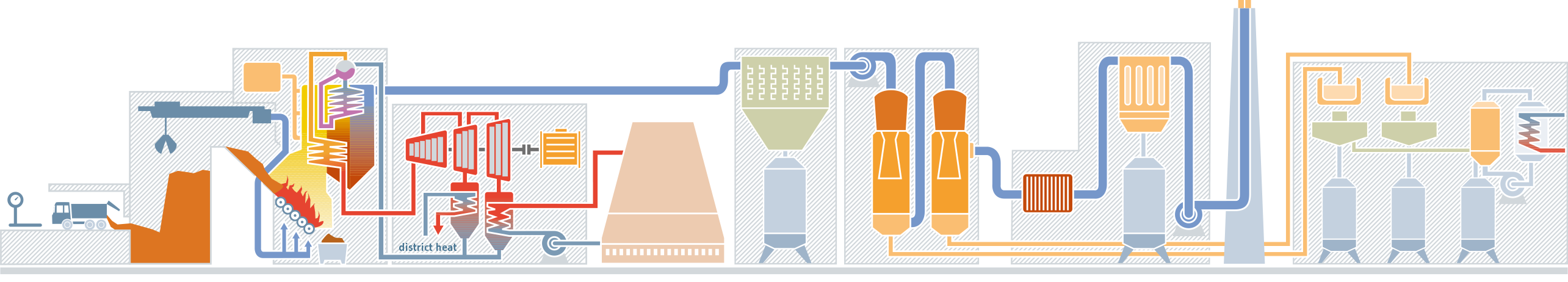
Weighing station
Every truck is weighed twice – before and after it has emptied its load. The difference in weight is equal to the volume of material delivered and this amount is then invoiced to the firm that delivered or produced the waste.
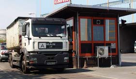
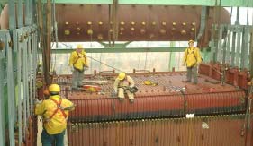
Waste bunker
The bunker can hold up to 26,000m3 of material and is filled via ten tipping bays equipped with hydraulic moving floors. There are two shears and three cranes in the actual bunker itself. The cranes have two main tasks: to prepare the waste for incineration by mixing and turning it to create a mixture that is as homogenous as possible and to fill the four boilers. Each grab crane is able to pick up around five tonnes of material in one go. The cranes are operated around the clock by teams of personnel working in five shifts. This allows us to keep our plant up and running 365 days a year.
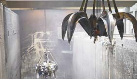
Incineration
The waste reaches the boilers via feeder hoppers. These boilers are the centrepiece of our plant and can reach temperatures of up to 1,200°C in their main combustion zones. Inside the boiler, a roller grate transports the waste through the various incineration stages: the drying, degasification, ignition, main combustion and burn-out zones. Together, all four incineration lines have a total heat output of 270 MW. The ‘17. BImSchV’ [17th Ordinance of the Federal Emissions Control Act] stipulates that the reaction gases generated by the incineration process must be kept at a temperature of 850°C for at least two seconds after the final combustion air supply to ensure any dioxins are safely destroyed.
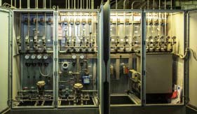
SNCR process
The flue gas reduction process begins at the place where the gases are generated: in the boiler. An ammonia solution is used as a reducing agent and injected into the system – but not until the temperature in the boiler is between 880°C and 1,000°C as this is when the NOx reduction process is most effective. The injection of ammonia is temperature-controlled via the plant’s process control system.
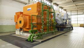
Steam generator
Each boiler is connected to its own steam generator, which are all operated under a pressure of 40 bar and at a temperature of 400°C. These comparatively low parameters – possible thanks to the state-of-the-art technology used – ensure that damage caused by corrosion is kept to a minimum. The results are lower repair costs and greater plant availability. Together these steam generators produce a total 305t of steam an hour.
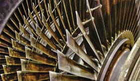
Turbine
The chemical energy released by the incineration process is transformed into thermal energy. The flue gases, heated up to 1,000°C, transfer their thermal energy to the steam system. The steam produced in the boilers is then fed into the two extraction condensing turbines to drive the generators attached to them. Whenever required, steam is removed ahead of the condensing section of the turbines to produce district heat in our combined heat and power system – up to 150,000 MWh a year. The remaining steam is fed into the final part of the turbines’ condensing section. The steam, which by this stage has expanded into a vacuum, is then condensed in the condenser before being returned to the boilers.
Generator
The plant’s two generators (output of 26 MW and 45 MW respectively) transform mechanical energy into electricity. All in all, they generate approx. 340,000 MWh every year. By the way, GMVA is completely self-sufficient as far as energy is concerned, i.e. it supplies itself with all the electricity it needs. The same is true for the heat it requires.
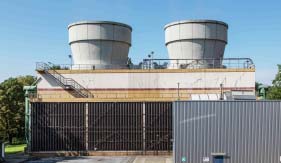
Cooling tower
Any steam that has not been fully condensed in the turbines must be condensed back into water in the condensers to close the power plant’s steam circuit. Two cooling towers (total circulation water quantity: 9,000 and 4,000 m3/hour respectively) ensure that the heat transmitted by the condensation process is cooled back down again.
Electrostatic precipitator
Each boiler has its own flue gas cleaning system, each with a capacity of 131,000m3 per hour. The flue gases are fed through the electrostatic precipitator as soon as they exit the boiler to remove any particulates. An electrostatic field is created here causing the particulate matter to settle on the surface of the collecting plates.
HCI scrubber
The first scrubbing stage of the flue gas abatement system – the so-called HCl scrubber – has an acidic environment (pH <1) and removes hydrogen chloride, any remaining particulate matter, heavy metals and dioxins from the flue gases.
SO2 scrubber
The SO2 scrubber then removes any remaining acidic pollutants, separating them from the flue gas. A sodium hydroxide solution is used to bind the sulphur dioxide with the scrubber slurry and so form salt-like sodium and calcium sulphite.
Fabric filter
Once they leave the SO2 scrubber, the flue gases (saturated in steam) are heated up to 115°C by a steam-heated tubular heat exchanger. A mixture of lime and coke is added at the entrance of the fabric filter creating a filter cake on the 1,440 fabric filter tubes which the flue gases must then pass through. This adsorbs and binds any other heavy metal compounds, dioxins and furans that may still be in the flue gas.
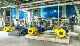
Wastewater treatment facility
This is where the wash water from the flue gas scrubbers is treated. The heavy metals are first precipitated from the bleed off water from the first scrubbing stage (> HCl scrubber) by adjusting the pH levels. The wastewater from the second cleaning stage is then mixed with the water from the first stage to create a gypsum slurry.
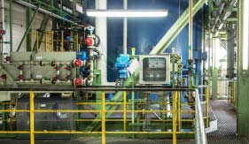
Evaporation plant
The wastewater is concentrated to approx. 25% of its original volume. The distillate from the evaporation process is recovered and re-used by the plant as process water. Approx. 5 - 8% of the contents of the residual brine are solids (primarily sodium chloride).

